Comparison between the coronal diameters of the cervical spinal canal and spinal cord measured using computed tomography and magnetic resonance imaging in Korean patients
Article information

Abstract
Background
If the proportion of the spinal cord in the epidural space can be determined under C-arm fluoroscopy during cervical epidural block, a safe entry point for the epidural needle can be established. The aim of this study was the measurement of the cord to canal transverse diameter ratio of each cervical spines.
Methods
We retrospectively evaluated the imaging data of 100 patients who underwent both cervical computed tomography (CT) and cervical magnetic resonance imaging (MRI) at our hospital. We measured the diameters of the spinal canal and spinal cord from the 3rd cervical vertebra to the 1st thoracic vertebra (T1) at each level by using the patients’ cervical CT and MRI images. The spinal cord and spinal canal diameters were measured in the transverse plane of the cervical MRI and CT images, respectively.
Results
The spinal cord to spinal canal diameter ratio was the highest at the 4th and 5th cervical vertebrae (0.64 ± 0.07) and the lowest at T1 (0.55 ± 0.06, 99% CI [0.535, 0.565].
Conclusions
Our findings suggest that the cord to canal transverse diameter ratio could be used as a reference to reduce direct spinal cord injuries during cervical epidural block under C-arm fluoroscopy. In the C-arm fluoroscopic image, if an imaginary line connecting the left and right innermost lines of the pedicles of T1 is drawn and if the needle is inserted into the outer one-fifth of the left and right sides, the risk of puncturing the spinal cord would be relatively reduced.
Introduction
Cervical epidural nerve block is commonly used for the treatment of neck pain and radiating pain in the upper extremities due to cervical disc herniation or postherpetic neuralgia [1–5]. The interlaminar and transforaminal approaches are commonly used for cervical epidural nerve block. Compared to the interlaminar approach, the transforaminal approach enables more effective injection of drugs that reduce inflammation and nerve edema to the target lesions. However, the transforaminal approach might result in serious complications, such as spinal radicular artery damage or spinal cord infarction, during particulate steroid injection or epidural needle positioning [6–8]. Therefore, the cervical interlaminar approach with nonparticulate steroid injection is recommended [9,10]. However, this approach could also result in serious complications, such as quadriplegia due to inadvertent intramedullary injection or spinal cord injury, even when performed under C-arm fluoroscopy [11,12].
Therefore, we aimed to identify a safe needle insertion point that can avoid cervical cord punctures as far as possible when performing cervical epidural block using the interlaminar approach under C-arm fluoroscopy. To date, most studies have suggested measuring the cervical cord diameter and cervical cord to canal ratio in the sagittal plane to predict the risk of cervical cord injury after trauma [13–16]. To our knowledge, this is the first study to investigate the utility of the cervical cord to canal diameter ratio for a safer interlaminar approach, which represents the cervical cord to epidural space diameter in the coronal plane.
Cervical interlaminar epidural block is usually performed in the prone position under C-arm fluoroscopy. We presumed that if the ratio of the cervical cord to epidural diameter in the posteroanterior (PA) view under C-arm fluoroscopy could be calculated, the percentage of spinal cord punctures could be reduced by positioning the epidural needle at more lateral and safer levels. The epidural space diameter could be measured as the innermost distance between the left and right pedicles under the C-arm fluoroscopy PA view, but the C-arm image is a magnified image. Therefore, we postulated that the transverse diameter of the epidural space under C-arm fluoroscopy could be measured via computed tomography (CT) because bony structures can be clearly visualized under CT, and the transverse diameter of the cervical cord could be measured via magnetic resonance imaging (MRI) at the same point. Accordingly, the primary outcome of this study was the measurement of the cord to canal transverse diameter ratio, i.e., the cord to epidural space transverse diameter ratio of each cervical vertebral level from the 3rd cervical vertebra (C3) to the 1st thoracic vertebra (T1). We also aimed to determine the differences in the cord to canal transverse diameter ratio according to the age, sex, height, and body weight of the included patients.
Materials and Methods
This study was approved by the Institutional Review Board of Daegu Catholic University Hospital (CR-21-045). This study was conducted in accordance with the ethical principles of the Helsinki Declaration-2013 and followed good clinical practice guidelines. The study included 100 patients (50 men and 50 women aged 20 to 70 years old) who visited our hospital and underwent both cervical CT and MRI simultaneously and whose medical records from December 1, 2020, through study completion, an average of two years were investigated retrospectively (Table 1). We excluded patients who had a history of cervical spine surgery or cervical cord edema, whose CT or MRI images did not include all the cervical vertebrae from C3 to T1, and who had at least one missing medical detail such as diagnosis, age, height, or weight.

Demographic Characteristics
The spinal canal diameter, i.e., the epidural transverse diameter, was measured as the distance between the innermost border of the left and right pedicles at each upper pedicular level from C3 to T1 on transverse CT images by using a picture archiving and communication system (PACS; INFINITT PACS G3, INFINITT Healthcare, Korea) (Fig. 1). The spinal cord transverse diameter was measured between the left and right outermost distances of the cord at each upper pedicular level, which were almost the same locations used for measuring the spinal canal diameter, from C3 to T1 on transverse MRI images by using the PACS (Fig. 2). All measurements were performed three times by an anesthesiologist, and the average values were used as data in the analyses.
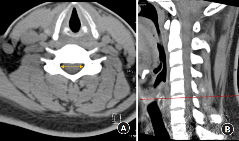
(A) Cervical canal diameter measured using a CT image. (B) Landmarks used to measure the cervical canal diameter. CT: computed tomography.
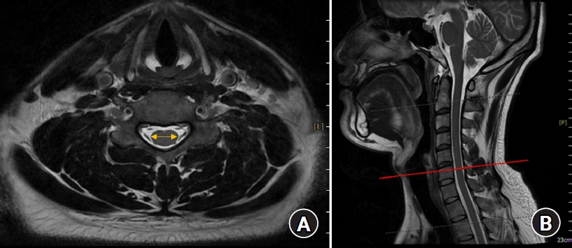
(A) Cervical cord diameter measured using a MRI. (B) Landmarks used to measure the cervical cord diameter. MRI: magnetic resonance image.
Summary for general characteristics were performed using descriptive analysis, the values of mean and standard deviation (SD) presented for quantitative variables, and the values of frequency and percent for qualitative variables. Comparison result for spinal canal transverse diameter, spinal cord transverse diameter, and ratio of the cord to canal transverse diameter were analyzed using repeated measure one factor analysis. Comparison result for spinal canal transverse diameter, spinal cord transverse diameter, and ratio of the cord to canal transverse diameter by demographic characteristics and interaction effects were analyzed using repeated measure two factor analysis. Multiple comparison result was performed by contrast under Bonferroni correction. The data analysis was performed by a medical statistician. All statistical analyses were performed using the IBM SPSS Statistics for Windows, version 19.0 (IBM Corp., USA). And all tests were two-sided and a P value of less than 0.05 considered to indicate statistical significance.
The sample size was calculated on the basis of the findings of a previous study [13] in which the ratio of the anteroposterior (AP) diameter of the spinal cord to the size of the spinal bony canal was 51.5 ± 5.7% and 46.5 ± 6.1% at C3 and the 7th cervical vertebra (C7), respectively. Accordingly, the number of patients required for a type I error of 0.05 and a power of 80% was 100.
Results
The transverse diameter of the spinal canal measured on CT was 20.4 ± 1.54 mm at C3, and it was longer than that measured at T1 (17.87 ± 1.47 mm). The diameter was the longest (20.7 ± 1.56 mm) at the 5th cervical vertebra (C5), and the diameters gradually shortened at the lower cervical vertebrae (Table 2). The transverse diameter of the spinal cord measured on MRI was the longest at C5 (13.25 ± 0.95 mm) and the shortest at T1 (9.80 ± 0.76 mm) (Table 3). The cord to canal transverse diameter ratios, namely the cord to epidural space transverse diameter ratio of each cervical vertebral level, were the highest at the 4th cervical vertebra (C4) and C5 (0.64 ± 0.07) and the lowest at T1 (0.55 ± 0.06, 95% CI [0.538, 0.562], 99% CI [0.535, 0.565]). The cord to canal transverse diameter ratios were significantly lower at T1 than at C3, C4, C5, 6th cervical vertebra (C6), and C7. The cord to canal transverse diameter ratios were also significantly lower at C7 (0.57 ± 0.07, 95% CI [0.556, 0.584], 99% CI [0.552, 0.588])than at C3, C4, C5, and C6 (Table 4, Fig. 3). However, no significant difference was observed according to sex, age, height, weight, and the body mass index.
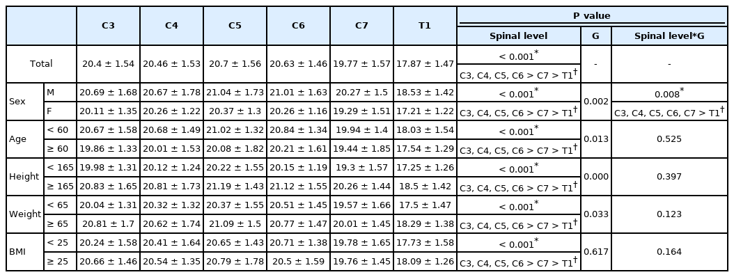
Spinal Canal Transverse Diameter (Width) at Each Upper Pedicular Level in the Coronal Plane Measured Using CT

Spinal Cord Transverse Diameter (Width) at Each Upper Pedicular Level in the Coronal Plane Measured Using MRI
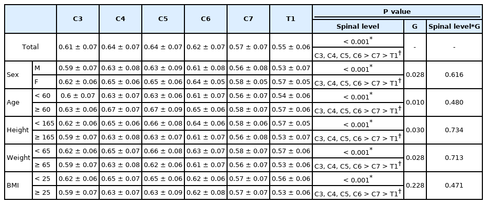
Ratio of the Transverse Diameter (Width) of the Spinal Cord/Spinal Canal at Each Vertebral Level
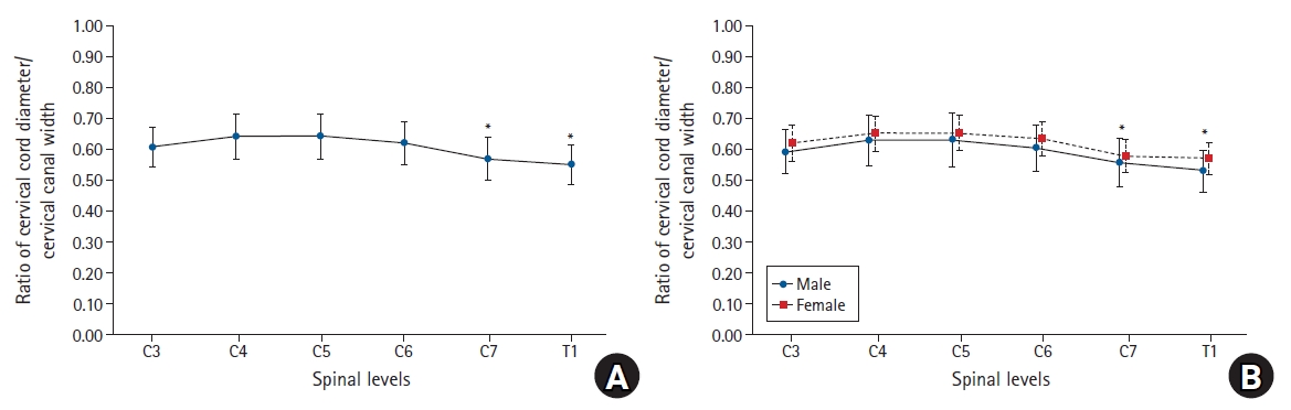
Graphs showing the ratio of the cervical cord/cervical canal diameter at each level. (A) The cord to canal diameter ratios were significantly lower at C7 and T1 than at C3, C4, C5, and C6. (B) There was no significant difference according to sex. *Statistically significant at P < 0.05.
Discussion
On comparing the transverse diameters of the spinal canal and spinal cord by using CT and MRI, the cord to canal diameter ratio was the highest at C4 and C5 and the lowest at T1. In this study, the T1 level was close to the C7 to T1 interlaminar foramen because the diameters of the spinal canal and spinal cord were measured at the upper pedicular levels. If epidural block was performed under C-arm fluoroscopy, the T1 level would be the safest injection site to reduce spinal cord injuries during cervical epidural block, as shown in previous reports [12]. Considering that the cord to canal transverse diameter ratio increases as we move to the upper cervical vertebrae, performing an epidural nerve block at levels higher than C6–7 and C7–T1 would increase the probability of spinal cord injury. Assuming the spinal cord was located in the middle of the vertebral body in the coronal plane and epidural block was performed at the T1 level, we could postulate that the risk of direct spinal cord puncture by the epidural needle would be reduced if the needle was inserted in the outer one-fifth region when an imaginary line was drawn between the innermost site of the pedicle under C-arm fluoroscopy, because the cord to canal diameter ratio at this site was the lowest (Fig. 4). In other words, assuming that the transverse diameter of the spinal canal is 1, the mean value, 95% CI, and 99% CI values of the cord to canal transverse diameter ratio are less than 0.6. This means that the outer sum of the cord is over 0.4; therefore, the possibility of having spinal cord in the outer one-fifth region of the transverse spinal canal on both sides is extremely low.
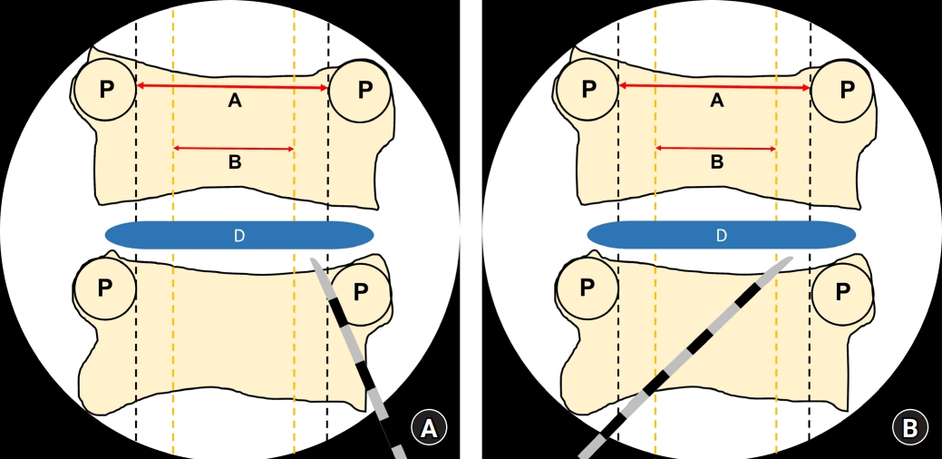
Schematic figure showing the imaginary lines that are observed using C-arm fluoroscopy during the cervical epidural block. The epidural needles are placed in the outer one-fifth of the cervical canal width by paramedian (A) and modified paramedian (B) approaches. The cervical cord will be in the inner three-fifth of the cervical canal width. A: cervical cord width, B: cervical epidural width, D: intervertebral disc, P: pedicle.
If cervical interlaminar epidural nerve block was performed by inserting the needle to the outside as much as possible, it would result in effective left or right unilateral block. Although this is an imaginary line, if the operator performs the cervical epidural nerve block along this virtual line, direct damage to the spinal cord caused by the needle could be reduced or prevented. However, the present study describes the location where the cord cannot be directly pierced with a needle as much as possible using images, and it is not a study that was actually conducted on patients. When positioning the needle on the outer one-fifth of the cervical canal under the C-arm AP image during the cervical epidural block, it should be considered that the ligamentum flavum is thinner as it goes outward rather than in the center, and if the needle is pierced too deeply, it can cause root injury.
Complications that may occur during cervical epidural nerve block include rare and serious ones like spinal cord injury, epidural hematoma, and epidural abscess, as well as minor ones like post-dural puncture headache and paresthesia [17]. All the reported cases of spinal cord injury during cervical epidural nerve block occurred under deep sedation [12,18]. Therefore, performing the procedure under arousal or under appropriate sedation is recommended so that the patient’s response can be immediately confirmed during the procedure and potential injuries can be avoided or reduced. In addition, because the ligamentum flavum of the cervical spine has a fusion defect rate ranging from 51% to 74% depending on the level of the cervical spine, the possibility exists that the operator might not feel the loss of resistance when performing an epidural block using the midline approach [19].
Stanley et al. [20] reported that the spinal canal AP diameters measured in the sagittal plane were shorter at C3, C4, and C5 than at other levels. The cross-sectional area of the spinal canal was the smallest at C4 and C7. Inoue et al. [15] used CT myelography and reported that the spinal canal AP diameter and spinal cord AP diameter in the sagittal plane decreased gradually from the C3 to C6 levels. Similarly, the transverse diameters measured from the axial image in the present study gradually decreased from cranial to caudal levels. On average, the spinal canal AP diameters range from 15.33 to 20.46 mm from C1 to C7 in the sagittal plane, with the longest diameter at C1 and the shortest at C4 [21,22]. Moreover, the sagittal canal diameters are shorter in females than in males by approximately 1 mm [21]. Ishikawa et al. [14] reported that the mean spinal cord areas in the coronal plane were the widest at C4 and in the 20s, but it decreased with age. Nakashima et al. [13] reported that the spinal canal diameter did not correlate with the spinal cord diameter, but correlated with the AP diameter of the dura mater in the sagittal plane. They also reported that the AP diameter of the spinal cord was approximately 50% of that of the spinal canal and the AP diameter of the spinal cord was approximately 60% of that of the dural sac in the sagittal plane. In the present study, the ratio of the transverse diameter of the spinal cord to that of the epidural space obtained from the axial images was in the range of 0.55 to 0.64, showing similar results to the previous study that measured the AP diameters in the sagittal plane.
This study also has a few limitations. Although CT is very useful for visualizing bony structures, it does not allow the measurement of the exact diameter of the spinal cord. Therefore, in this study, the diameter of the spinal canal was measured using CT, and the diameter of the spinal cord was measured using MRI, which helped accurately visualize the structure of the spinal cord. Consequently, although the measurement location was set to each pedicle, some errors may have been introduced because the measurement point was not identical in CT and MRI. However, since the images were acquired at intervals of 1 mm, the difference was insignificant. In addition, CT or MRI cross-sections were not always obtained perpendicular to the cross-sectional area during diameter measurements. Nevertheless, since we measured transverse but not AP diameters, the diameters of the spinal cord and spinal canal should be identical even if the image slice was not cut vertically, and hence, this variation did not affect the length measurements. Finally, the MRI or CT of a patient is taken in the supine position, while an actual epidural block is performed in the prone position with neck flexion. Furthermore, in the prone position with neck flexion, the cervical cord moves to the ventral side and is tented; therefore, it may not exactly match the cord to canal diameter ratio measured in this study and that in the actual epidural block. In the sagittal plane, as the cervical cord moves to the anterior space in the prone position with neck flexion, the length of the posterior epidural space can be significantly increased. However, in the coronal plane, even if the cord moves to the anterior space, there is no significant difference in the cord width; consequently, there may be no significant change in the cord to canal transverse diameter ratio according to the position.
In conclusion, we measured the transverse diameters of the cervical spinal canal and spinal cord and calculated the spinal cord to spinal canal diameter ratios at various cervical vertebrae and found that the ratios were the smallest at T1 and the largest at C4 and C5. By using our data as reference, cervical epidural nerve block under C-arm fluoroscopy could be performed after considering the location of the imaginary spinal cord in order to potentially avoid serious side effects such as direct spinal cord punctures.
Notes
Funding
None.
Conflicts of Interest
No potential conflict of interest relevant to this article was reported.
Author Contributions
So Young Lee (Investigation; Writing – original draft)
In Young Kim (Data curation; Investigation; Methodology; Project administration; Resources)
Kyung Wook Jeong (Data curation; Formal analysis; Investigation; Methodology; Visualization)
Taeha Ryu (Data curation; Project administration; Software)
Sang Kyu Kwak (Data curation; Formal analysis; Software)
Jin Yong Jung (Conceptualization; Methodology; Supervision; Validation; Visualization; Writing – original draft; Writing – review & editing)