Three-dimensional pelvis computed tomography-assisted Taylor approach for spinal anesthesia in hip arthroplasty: a retrospective study
Article information

Abstract
Background
Needle insertion for spinal anesthesia using the Taylor approach is challenging as the L5-S1 space is difficult to locate from the surface anatomy. In this study, we suggest the use of three-dimensional (3D) pelvis computed tomography (CT) to assist anesthesiologists in locating the needle insertion point. By comparing the success rate of 3D pelvis CT-assisted Taylor approach to that of other approaches in the existing literatures, we suggest this technique as an alternative method for subarachnoid block in the L5-S1 space.
Methods
In this retrospective observational study, we reviewed the records of hip arthroplasty using the 3D pelvis CT-assisted Taylor approach. An imaginary guidance line was created from the intersection point of the midline and intercristal line on the posterior view of the 3D pelvis CT to the ideal skin insertion point for Taylor approach. The primary outcome was the success rate. The secondary outcomes included the angle between the intercristal line and the guidance line, and the length of the guidance line and the distance between the ideal needle insertion point and the L5-S1 space.
Results
We reviewed the records of the 276 patients who underwent hip arthroplasty using 3D CT-assisted Taylor approach. In this cohort, the 3D CT-assisted Taylor approach in L5-S1 subarachnoid block failed in only 25/276 patients. The success rate of 3D CT-assisted Taylor approach was 90.9%.
Conclusions
Three-dimensional pelvis CT-assisted Taylor approach of spinal anesthesia can be an alternative method for subarachnoid block in the L5-S1 space with an acceptable success rate.
Introduction
Performing spinal anesthesia can be challenging in some elderly patients. Spinal deformities due to aging, postoperative surgical scars, and metallic instrumentation during spinal surgery are major obstacles to the success of spinal anesthesia. Gupta et al. [1] concluded that Taylor’s approach could be a reliable and less traumatic alternative to the midline approach for lumbar puncture in deformed spine. The Taylor’s approach of spinal anesthesia, which is performed in the L5-S1 interlaminar interspace can solve this problem.
In the Taylor approach, a spinal needle is inserted in the cephalomedial direction through a skin wheal raised 1 cm medial and 1 cm caudal to the lowermost prominence of the posterior superior iliac spine (PSIS) [2]. However, it is challenging for a beginner to analyze the patient’s surface anatomy to localize the needle insertion point that needs to reach to the L5-S1 space (target). The needle insertion point is supposed to be situated near the ‘skin dimples,’ which corresponds to the lowermost prominence of the PSIS. However, not all elderly patients have remarkable skin dimples on their lower back. In addition, it is difficult to estimate the location of the target (L5-S1) space. The ‘cephalomedial direction’ is all the information a novice anesthesiologist is provided to imagine its position. These two obstacles prompted us to focus on the three-dimensional (3D) pelvis computed tomography (CT).
Anesthesiologists utilize the measurements from radiological studies to decide the correct needle insertion depth and direction for the spinal anesthesia. When we had planned a Taylor approach for the spinal anesthesia, the pelvis 3D CT had benefited us in identification of the needle insertion point and direction towards the target space. Analysis of the three dimensional bony structures allowed us to easily identify the anatomical landmarks.
We assumed that the success rate of the Taylor approach would be acceptable when anesthesiologists use the 3D CT to identify the needle insertion point. We compared our success rate to those calculated in other studies to prove this hypothesis. Zhang et al. [3] previously reported the success rate of an elevated lateral recumbent position (ELP) and the regular lateral recumbent position (LRP) with the paramedian approach to the subarachnoid space. Successful dural puncture within two attempts of the ELP and the LRP had success rates of 97.8% and 82.8%, respectively [3]. Gupta et al. [1] reported a failure rate of 15% with the conventional Taylor’s approach. Our primary outcome was the success rate of the 3D CT-assisted Taylor approach, and the secondary outcomes were the mean values of the angles and lengths leading to the needle insertion point. Additionally, we analyzed whether patient factors, such as body mass index (BMI), scoliosis, kyphosis, and spinal instrumentation, would have a negative impact on the success of this technique.
Materials and Methods
This was a retrospective observational study in a single center. After obtaining approval from the Institutional Review Board (IRB no. 19RESI0047) of Daejeon St. Mary’s Hospital (Daejeon, Korea), the medical records of 280 patients who underwent hip arthroplasty with 3D pelvis CT from March 2018 to May 2019 were assessed for eligibility for this study. All the procedures were conducted in accordance with the Helsinki Declaration-2013.
Four cases were excluded from the review (Fig. 1) as their conditions were not suitable for the subarachnoid block. The exclusion criteria were (1) International Normalized Ratio (INR) over 1.5, (2) warfarin treatment within 5 days, (3) platelet number of below 100,000 microliters of blood, (4) patient refusal, and (5) noncooperation due to confused mental status. Only one anesthesiologist attempted 3D pelvis CT-assisted Taylor approach for the spinal anesthesia. The following two conditions were requisite for the success of the 3D CT-assisted Taylor approach: (1) free flow of cerebrospinal fluid following a maximum of five trials of dural puncture, (2) no complaints of pain relating to the surgical incision. The number of trials is defined as the number of skin punctures. Angles and lengths for the identification of the needle insertion point was measured from the 3D pelvis CT and the imaginary target distance from the needle insertion point was estimated from the 3D pelvis CT. Data on BMI were collected, and spinal deformities, such as compression fracture, kyphosis, scoliosis, metallic instrumentation, and vertebroplasty, were analyzed using a simple L-spine radiograph interpreted by the radiologists.

The exclusion criteria from the review. 3D: three-dimensional, CT: computed tomography, INR: International Normalized Ratio.
Clinical practice of 3D pelvis CT-assisted Taylor approach in the operating room
Informed consent was obtained from patients who were scheduled for a hip arthroplasty. The 3D pelvis CT of the patients scheduled for surgery was confirmed by one physician. We determined the needle insertion point and the target (L5-S1) space for the Taylor approach (Fig. 2) with the following procedure:

Clinical practice of 3D pelvis CT-assisted Taylor approach in the operating room. 3D: three-dimensional, CT: computed tomography.
From the posterior view of the 3D pelvis CT, we selected the image wherein the symphysis pubis met the midline. (1) The needle insertion point for the Taylor approach (A) was 1 cm medial and 1 cm caudal to the PSIS. (2) The target (T) is defined as the point where the midline meets the L5-S1 interlaminar space. (3) The intercristal line connects the two iliac crests. (4) The midline was perpendicular to the intercristal line. In the case of spinal scoliosis, the midline drawn on the sacrum was elongated to the lumbar area. (5) ‘B’ is the point where the intercristal line meets with the midline. (6) ‘X’ is the length between B and A. (7) ‘Y°’ is the angle between the intercristal line and the B-A line. (8) ‘X cm’ and ‘Y°’ form a pair of length and angle representing the location of ‘A,’ and (9) ‘t cm’ is the length from B to the target (L5-S1) on the midline.
The procedure was performed with the patient in the sitting position on the bed after intravenous administration of midazolam 0.5–2 mg and fentanyl 50–100 µg. All procedures were performed with the aseptic method. The intercristal line and midline were drawn. From intersection B, we drew a line that was Y° down the intercristal line using a protractor. We marked ‘A’ as the point of needle insertion, X cm from B. Finally, the target (L5-S1 space: t cm from B) was located (Fig. 3). A 3.5-inch spinal needle was inserted toward ‘T’ through ‘A.’. If a bone was encountered on the first needle insertion, the needle was walked off the sacrum into the target (T; L5-S1 space). After confirming the free flow of cerebrospinal fluid, 20 mg of heavy bupivacaine was administered. After being transferred from the bed to the operating table, the patient was placed in the Trendelenburg position for a few minutes. The level of the block was confirmed by the pinprick test. Once the level of the block reached the T10 dermatome, the patient was switched to the lateral position for surgery. The patient was sedated with propofol infusion at a rate of 150–200 mg/h with an initial bolus of 30 mg. Capnography was used to monitor the patient’s breathing. All procedures in this study were performed by one anesthesiologist.

Determining the needle insertion point and the target (L5-S1) space for the Taylor approach on 3D pelvis CT. A: The needle insertion point for the Taylor approach. A was 1 cm medial and 1 cm caudal to the posterior superior iliac spine. T: The target point where the midline meets the L5–S1 interlaminar space. The intercristal line connects the two iliac crests. The midline was perpendicular to the intercristal line. B: The point where the intercristal line meets with the midline. X: The length between B and A. Y°: The angle between the intercristal line and B-A line. “X cm” and “Y°” form a pair of length and angle representing the location of “A” and “t cm” is the length from B to the target (L5–S1) on the midline. 3D: three-dimensional, CT: computed tomography, PSIS: posterior superior iliac spine.
Statistical analysis
The sample size was based on the available data during the study period. The means for continuous variables were compared using the unpaired Student’s t-test. The chi-squared test was used to compare categorical valuables, and P < 0.050 was considered statistically significant. All statistical analyses were performed using SPSS version 15 (SPSS Inc., USA).
Results
We reviewed the medical records of 280 patients who underwent hip arthroplasty with 3D pelvis CT from March 2018 to May 2019. Four patients were excluded from the study as they showed contraindications for subarachnoid block (Fig. 1).
Primary outcome
The success rate of 3D-CT assisted Taylor’s approach was 90.9%, and the number of trials between the success group and the failure group was 2.4 ± 1.6 and 5.6 ± 1.1 (P < 0.010), respectively (Table 1).
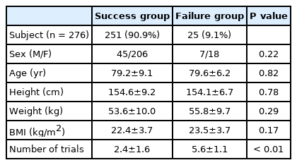
Demographic Data and Primary Outcomes in the Study Cohort
Secondary outcome
The needle insertion point A was located on a line approximately 65.5 ± 5.8° from the intercristal line (success group: 65.5 ± 6.4°, failure group: 65.6 ± 4.9°) (P = 0.961) and 5.9 ± 0.6 cm from point B (success group: 5.9 ± 0.7 cm, failure group: 5.9 ± 0.4 cm) (P = 0.810). The target (L5-S1 space) was 2.7 ± 0.6 cm (success group: 2.7 ± 0.5 cm, failure group: 3.1 ± 0.6 cm) (P = 0.030) from point B (Table 2).
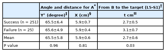
Secondary Outcomes Used for Locating Needle Insertion Points
BMI and spinal deformities such as compression fracture, kyphosis, scoliosis, metallic instrumentation, and vertebroplasty
The BMI was 22.4 ± 3.7 kg/m2 and 23.5 ± 3.7 kg/m2 (P = 0.172) in the success and failure groups, respectively. Compression fractures developed in 59% of women (men: 32%), kyphosis in 8% (men: 7%), scoliosis in 20% (men: 11%), metal instrumentation in 13% (men: 7%), and vertebroplasty in 32% (men: 14%). The number of spinal deformities was 1.3 (failure: 1.1) and 0.7 (failure: 0.8) in women and men, respectively, in the success group with no statistically significant difference between the number of spinal deformities and the success rate.
Discussion
This study showed that spinal anesthesia using the 3D pelvis-assisted Taylor approach was successful in 90.9% of patients who underwent hip arthroplasty.
Spinal anesthesia is recommended for isolated orthopedic injuries, such as femoral neck fracture, owing to the lower mortality rate, shorter hospital stay, and lower incidence of delirium in the postoperative period for elderly patients [4]. However, spinal anesthesia in elderly patients is more time-consuming and has lower success rates than that in young patients. This has led some anesthesiologists to attempt the Taylor approach. The L5-S1 space is not only wider than the other intervertebral spaces [5], but is also the most suitable space for the spinal block when other interspaces are not easy to approach due to spinal deformities [1].
In our center, 3D pelvis CT is always prescribed by orthopedic surgeons for their surgical procedure [6]. This imaging modality provides more stereoscopic vision than simple X-ray or 2D-CT, and anatomical landmarks are more distinctive on 3D pelvis CT than other imaging studies.
The success rate of the 3D pelvis CT-assisted Taylor approach was 90.9% in our study, which is comparable with that of other studies. Zhang et al. [3] reported the success rate of an ELP and the regular LRP with the paramedian approach to the subarachnoid space. Successful dural puncture within two attempts of the ELP and the LRP had success rates of 97.8% and 82.8%, respectively [3]. Gupta et al. [1] reported a failure rate of 15% with the conventional Taylor’s approach. There were no significant statistical differences between the number of spinal deformities and the success rate. Contrary to anesthesiologist’s expectations, the number of spinal deformities had no negative contribution to the success of the 3D pelvis CT-assisted Taylor approach. This could be explained by the fact that the L5-S1 space is the widest despite pathological spinal diseases.
This study leaves three questions unsolved. First, the comparison between the 3D pelvis CT-assisted approach and the usual Taylor approach needs to be expanded upon. A prospective control study is needed to prove that the 3D pelvis CT-assisted Taylor approach is superior to other approaches. Second, the pelvic CT is performed in a supine posture whereas the 3D pelvis CT-assisted Taylor approach is performed in a sitting position. The difference between those two postures may affect the results, and a related analysis is further required. Lastly, the entire medical records for the analysis revealed that only one anesthesiologist had performed the 3D pelvis CT-assisted Taylor approach in this. Thus, the primary outcomes may depend on the anesthesiologist’s proficiency with the technique. The fact that the success group had no statistically significant difference between the number of spinal deformities and the success rate empowers this possibility. Further studies are needed to reflect this factor in extracting the primary outcome.
In our conclusion, 3D-pelvis CT-assisted Taylor approach can be an alternative approach useful for locating the spinal needle insertion point and the target (L5-S1) space in hip arthroplasty with acceptable success rate.
Notes
Funding
None.
Conflicts of Interest
No potential conflict of interest relevant to this article was reported.
Data Availability
The datasets analyzed during the current study are available from the corresponding author on reasonable request.
Author Contributions
Saecheol Oh (Conceptualization; Data curation; Formal analysis; Investigation; Methodology; Project administration; Resources; Software; Validation; Visualization; Writing – original draft; Writing – review & editing)
Yoojung Park (Writing – original draft; Writing – review & editing)
Hana Kwoun (Conceptualization; Methodology)
Eunjin Eom (Project administration; Writing – original draft)
Dal-ah Kim (Supervision)